In my last article I discussed Creating Flexible, Robust Workflows: Switch & Loop. The basic idea is that large workflows should be modified so that they can be recovered at any state, and tested more easily. I introduced a way to do this in Nintex, the “Switch and Loop”. The Switch and Loop has some benefits, but it also has its drawbacks. Namely, by relying on list updates, it is possible that the workflow could fail in some circumstances due to conflicts during a list item update. While we covered ways to mitigate this issue, ideally, we’d be able to avoid it.
This article will discuss an alternate way of designing a flexible workflow that allows us to avoid conflicts for list items by decoupling state transitions from what is happening on the list, except for the moment when the workflow is kicked off. For this additional robustness, the costs are an additional delay when reaching the first step of a workflow, and a potential loss of control over workflow execution.
While the Switch and Loop can theoretically give us control of workflow execution while a workflow is in progress, the design covered in this post will only provide control over the initial executing branch.
The alternate design: A Switching State Machine
A Switching State Machine is a way to control workflow execution. This means that it allows a user to start a workflow at any stage in a process. This can be used to recover more gracefully from errors, as well as greatly speed up testing by focusing only on certain parts of a workflow.
To do this, we will execute a switch at the beginning of a state machine that will give us the ability to control the initially executing branch of a workflow. By updating the list item during state changes, we view the status in the list as well.
The section below describes how to implement this design.
To start, we’ll need a switch
For this design idea we’ll need a switch action connected to a list column. This will allow us to interact with a workflow.
So, to start create a choice column on a list with four options: Step 1, Step 2, Step 3, and Complete.

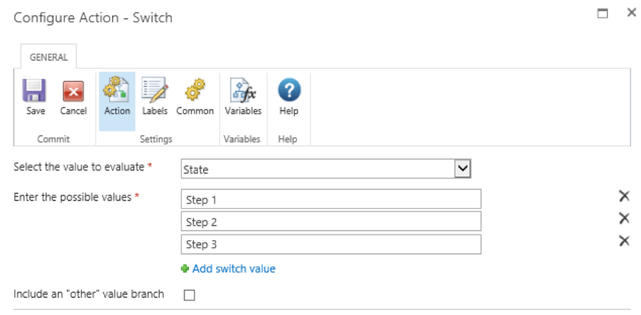
Next, create a new workflow and drop in a switch action that evaluates based on what is contained in the choice column you just created. Set the possible values to the first three choices you created.

Your switch should look like this.

Now, drop in a state machine action and create 4 states: Initialization, Step 1, Step 2, Step 3, and move the switch action to the initialization state. Make sure to set the initialization branch as the state the state machine will start in.

In the workflow designer, it should look something like what is below:

Next, add transitions to the branches of the switch so that the workflow will execute the desired branch first and then add transitions so that the workflow continues from Step 1 -> Step 2 -> Step 3.
At this point we have a workflow that can be started at any state and will continue until completion. This is because the workflow will start at the initialization branch and check which state it should execute in, then transition to that state. It will continue transitioning until thestate machine is completed.
One strength that this design has over the Switch and Loop, is that we can be certain that transitions will function correctly and we do not need to include complete pending actionactions to ensure that that the next desired state is read in time to transition to it.

We may want to see the currently executing state of a workflow from the list item without needing to view the workflow history. By adding update item actions, the current step can be shown on the state column of the list. The final version of our workflow might look something like this:

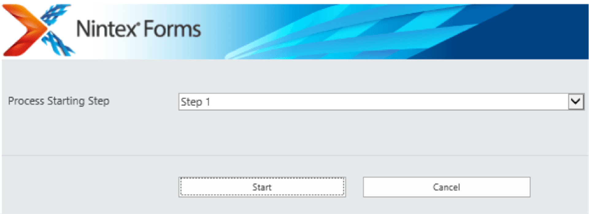
As with the Switch and Loop, it may be worthwhile to create a start form that will allow easy control of the starting state. This should only be done if regular users do not kick off workflows manually, since this control may cause a process to not follow the required steps.

Summary
Today, we covered an alternate way to design flexible workflows. Since we have now covered two alternate designs, a comparison is shown below. For many applications the process described above is likely the most appropriate choice. I’ve bolded the preferred solution for each dimension I’ve compared the two designs.
Find the List template here and the related workflow here.
Category Item Switching State Machine Switch and Loop Preferred Design Speed First Loop Execution Time After 5 minutes (based on SP Timer) Immediately Switch and Loop Speed Branch Transition time 5 Minutes 5 Minutes Equal Control Where control of execution exists For initial step At any step (though challenging to implement) Switch and Loop (slightly) Robustness How transition is done Using internal workflow logic Through communication with underlying list Switching State Machine Robustness Potential Errors Initial state not matching switch value List updates, state not matching switch value Switching State Machine